4.2 Resonators: measurement range 15 kHz to 20 MHz
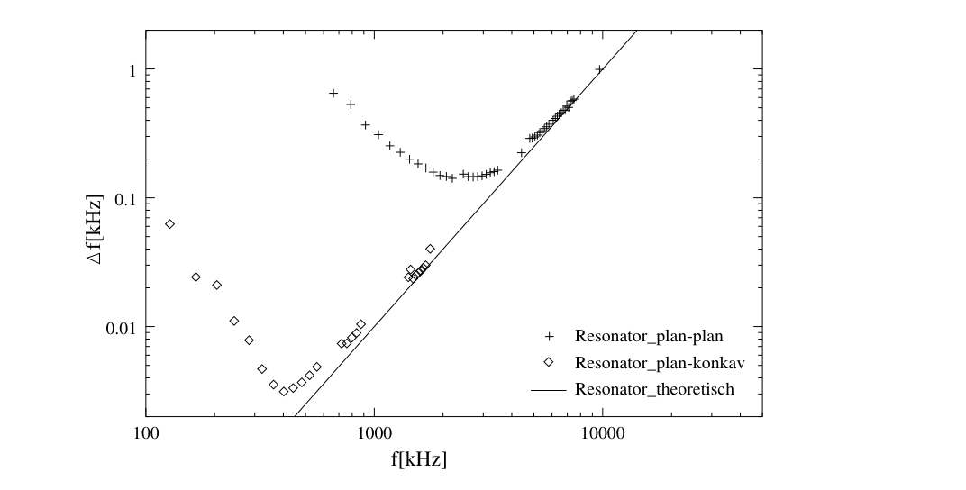
Figure 4.3. Measured half-width as a function of frequency for water at 25 °C; source: [27]. Comparison of the two resonators shows an increasingly pronounced deviation from the theoretical curve at low frequencies. Another conspicuous feature is the absence of measurement points corresponding to the following relation [28]:
fs = n · 0.627 · fquartz, with n ∈ ℕ.
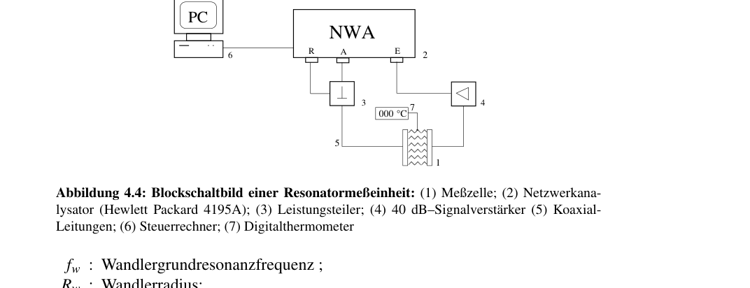
Figure 4.4. Block diagram of a resonator measuring unit: (1) measuring cell; (2) network analyzer (Hewlett Packard 4195A); (3) power splitter; (4) 40 dB signal amplifier; (5) coaxial cables; (6) control computer; (7) digital thermometer.
Symbols: fw, fundamental resonance frequency of the transducer; Rw, transducer radius; R, cell radius; l, cell length; fg, fundamental resonance frequency of the cell; V, volume; k, radius of curvature of the transducer.