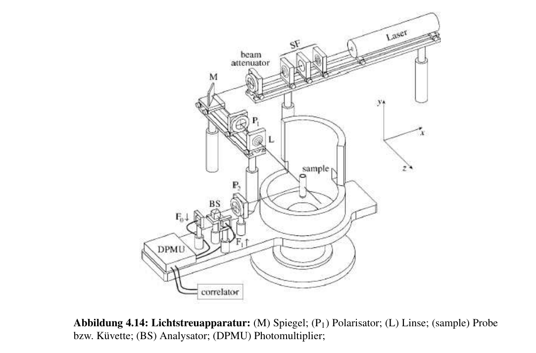
Figure 4.14. Light-scattering apparatus: M, mirror; P1, polarizer; L, lens; sample, sample or cuvette; BS, analyzer; DPMU, photomultiplier.
1. Down-conversion of the optical signal
The aim is to shift the high input frequencies into a range accessible to electronic detection. In general, a high-frequency input signal is mixed with a signal from an auxiliary oscillator. After mixing, the convolution theorem states that the spectrum of the photon current to be detected is described by the convolution of the input spectrum with itself. If the input spectrum is denoted by Aₑ, then:

Using Eq. (3.62), the spectrum of the photocurrent i(t) becomes:

This provides access to a quantity that can be measured directly, by means of autocorrelation.
Original mathematical notation and illustrations are preserved as extracted image assets.