As in the analysis of the resonator technique, the ideal case alone is insufficient: in a real system the reflection coefficient is not equal to unity. The correction formula follows from the impedance ratio of transducer to water, ZL/ZT ≈ 0.1, and a transducer resonance frequency fTm = 5 MHz. Eggers and Kaatze [39] give the final correction as

More detailed descriptions of the electronic circuitry and technical implementation are given in [44] and [40].
Figure 4.12 · Cross-section of the sound-velocity cell
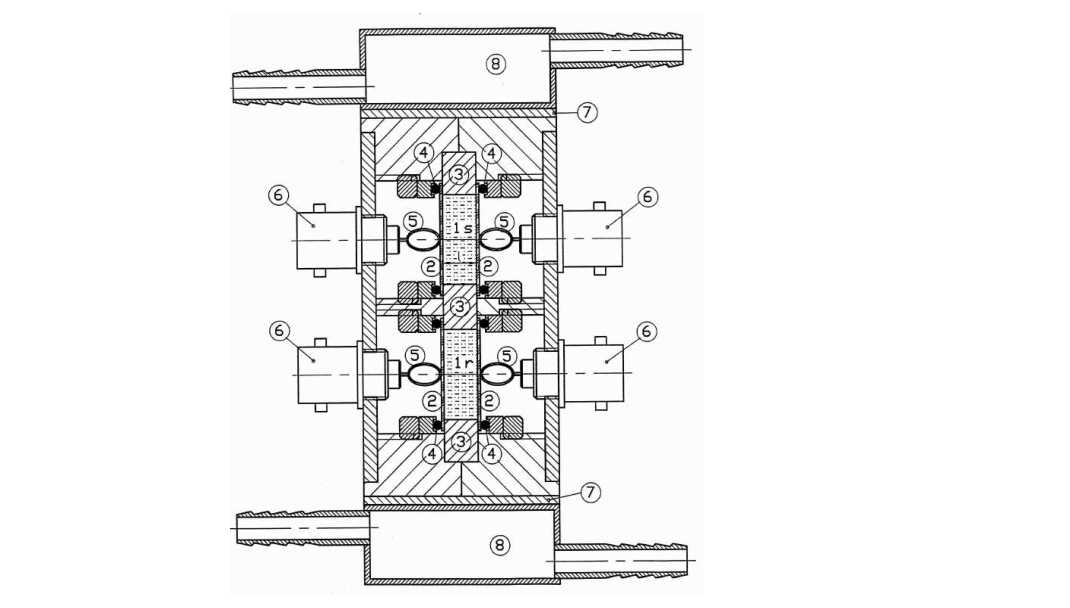
Figure 4.12. Cross-section of the sound-velocity measuring cell after [44]. (1s, 1r) Sample and reference resonators; (2) quartz transducers; (3) steel support; (4) sealing rings; (5) transducer contacts; (6) electrical connection; (7) Peltier element; (8) thermostating channels.
4.4.2 Measurement procedure
Each measurement on a new substance is preceded by a water measurement in the double cell. The purpose is to detect possible changes in the cell-length difference Δl caused by mechanical stress.
Original mathematical notation and figures are preserved in extracted image assets.