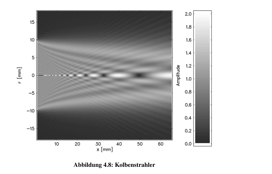
Figure 4.8: Piston radiator.
Here A is the surface area of the transducer, and:

4.3.3 Technical specifications and diagrams (ultrasonic transmission cells)
The ultrasonic transmission cells relevant to this thesis are the 1-MHz cell and the 10-MHz cell. The electronic circuits are shown in Figure 4.9. The technical parameters and the mechanical construction of the low-frequency ultrasonic transmission cell are presented in Table 4.3 and Figure 4.10, respectively.
4.3.4 General measurement procedure
The temperature-control and filling procedures are analogous to those used for the resonators. Here, too, a stable temperature must be achieved and the formation of air bubbles during filling must be avoided. At the beginning of the measurement, the zero point of the transducer separation has to be determined. This is done by carefully moving the transducer manually into the region where the ripple occurs. The abrupt disappearance of the λ/2 ripple during uniform manual adjustment of the transducer separation indicates that the zero point has been reached. The sound velocity of the substance is then determined so that, during the measurement, the signal shifted along the time axis by acoustic propagation through the medium can always be sampled at the same position.