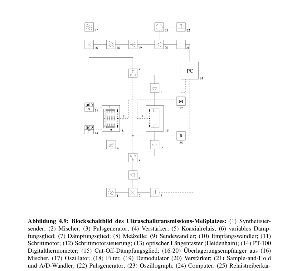
Figure 4.9: Block diagram of the ultrasonic transmission measurement station: (1) frequency synthesizer/transmitter; (2) mixer; (3) pulse generator; (4) amplifier; (5) coaxial relay; (6) variable attenuator; (7) attenuator; (8) measurement cell; (9) transmitting transducer; (10) receiving transducer; (11) stepping motor; (12) stepping-motor controller; (13) optical displacement sensor (Heidenhain); (14) PT-100 digital thermometer; (15) cut-off attenuator; (16–20) superheterodyne receiver comprising (16) mixer, (17) oscillator, (18) filter, (19) demodulator and (20) amplifier; (21) sample-and-hold circuit and A/D converter; (22) pulse generator; (23) oscilloscope; (24) computer; (25) relay driver board. Solid lines indicate signal connections; dashed lines indicate control connections.
Once these prerequisites for a successful measurement have been established, the measurement procedure can begin. The desired measurement frequency is selected, and the superheterodyne receiver is adjusted to the reference signal of the cut-off attenuator. The actual measurement follows the principle of ultrasonic measurement methods already introduced in Section 4.1. The computer determines the measurement path length until the signal level has fallen by 15 dB and converts the result into an attenuation value α/f².
A more detailed description of the ultrasonic transmission cells can be found in [33].