Figure 4.11 · Block diagram of the sound-velocity measuring cell
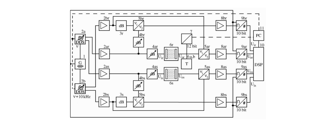
Figure 4.11. Block diagram of the sound-velocity measuring cell after [44]. Components marked (a) belong to the measurement signal, those marked (b) to the reference signal. (1) 50-MHz control-signal generator; (2a, 2b) digitally synthesized transmitters; (3) fixed attenuator; (4a, 4b) variable attenuators; (5a, 5b) mixers; (6) double-resonator cell; (6a, 6b) temperature-control units; (7) 12-bit D/A converter; (8) 10-kHz amplifier; (9a, 9b) A/D converters; (10) DSP processor board; (11) amplifier.
Here l denotes the resonator cell length and c the sound velocity in the liquid. The two resonator cells cannot be assumed to be identical: small differences in cell length must be allowed for.

These two relations can be combined to express the difference between the cell lengths:

The difference in cell length was determined from numerous measurements in which water, whose properties are well known, was placed in both cells [44]. With a reference substance of known sound velocity c1 and the calibrated length difference Δl, the unknown sound velocity c2 of the sample can then be determined:

Original mathematical notation and figures are preserved in extracted image assets.