Original English dissertation · scientific equations reproduced directly from the source PDF.
3.3 Ultrasonic techniques
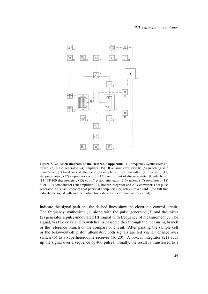
Figure 3.12: Block diagram of the electronic apparatus: (1) frequency synthesizer; (2) mixer; (3) pulse generator; (4) amplifier; (5) HF-change over switch; (6) matching stub transformer; (7) fixed coaxial attenuator; (8) sample cell; (9) transmitter; (10) receiver; (11) stepping-motor; (12) step-motor control; (13) control unit of distance meter (Heidenhain); (14) PT-100 thermometer; (15) cut-off piston attenuator; (16) mixer, (17) oscillator , (18) filter, (19) demodulator (20) amplifier; (21) boxcar integrator and A/D-converter; (22) pulse generator; (23) oscilloscope; (24) personal computer; (25) relays driver card. (the full line indicate the signal path and the dashed lines show the electronic control circuit).
indicate the signal path and the dashed lines show the electronic control circuit. The frequency synthesizer (1) along with the pulse generator (3) and the mixer (2) generates a pulse-modulated HF signal with frequency of measurement f. The signal, via two coaxial HF-switches, is passed either through the measuring branch or the reference branch of the comparator circuit. After passing the sample cell or the below-cut-off piston attenuator, both signals are fed via HF change over switch (5) to a superheterodyne receiver (16-20). A boxcar integrator (21) adds up the signal over a sequence of 400 pulses. Finally, the result is transferred to a
View original page 51 (authoritative equations, figures and layout)
Original dissertation · PDF page 51 · reader page 43 of 132