Original English dissertation · scientific equations reproduced directly from the source PDF.
3.3 Ultrasonic techniques
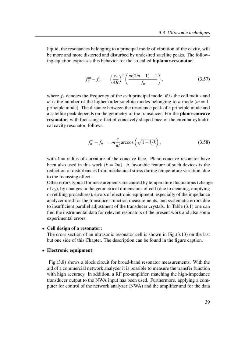
liquid, the resonances belonging to a principal mode of vibration of the cavity, will be more and more distorted and disturbed by undesired satellite peaks. The follow- ing equation expresses this behavior for the so-called biplanar-resonator:

where fn denotes the frequency of the n-th principal mode, R is the cell radius and m is the number of the higher order satellite modes belonging to n mode (m = 1: principle mode). The distance between the resonance peak of a principle mode and a satellite peak depends on the geometry of the transducer. For the plano-concave resonator, with focussing effect of concavely shaped face of the circular cylindri- cal cavity resonator, follows:

with k = radius of curvature of the concave face. Plano-concave resonator have been also used in this work (k = 2m). A favorable feature of such devices is the reduction of disturbances from mechanical stress during temperature variation, due to the focussing effect. Other errors typical for measurements are caused by temperature fluctuations (change of cs), by changes in the geometrical dimensions of cell (due to cleaning, emptying or refilling procedures), errors of electronic equipment, especially of the impedance analyzer used for the transducer function measurements, and systematic errors due to insufficient parallel adjustment of the transducer crystals. In Table (3.1) one can find the instrumental data for relevant resonators of the present work and also some experimental errors.
• Cell design of a resonator: The cross section of an ultrasonic resonator cell is shown in Fig.(3.13) on the last but one side of this Chapter. The description can be found in the figure caption.
• Electronic equipment:
Fig.(3.8) shows a block circuit for broad-band resonator measurements. With the aid of a commercial network analyzer it is possible to measure the transfer function with high accuracy. In addition, a RF pre-amplifier, matching the high-impedance transducer output to the NWA input has been used. Furthermore, applying a com- puter for control of the network analyzer (NWA) and the amplifier and for the data
View original page 45 (authoritative equations, figures and layout)
Original dissertation · PDF page 45 · reader page 37 of 132